This is a short tutorial on setting up external debug access to the ROCK64 board.
The Rock64 board uses SWD (two-wire) for debug access. The pins used for SWD are multiplexed with the MicroSD card data lines so you can't use both at once. These are also labelled with their JTAG function (TCK and TMS) but the other JTAG data lines are not pinned out on this chip so you must use SWD mode.
 |
| ROCK64 MicroSD Slot Schematic (Simplified) |
For a debug adapter I am using a RaspberryPi (the original single core version because I happen to have one of those laying around.) I am running OpenOCD as the JTAG software. There is a guide
here on how to set that up on a RaspberryPi. As long as you are running some variant of linux on your RaspberryPi it is pretty easy (just install dependencies, compile, and install.)
My configuration files for OpenOCD are available
here.
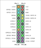 |
| P1 Header Pinout |
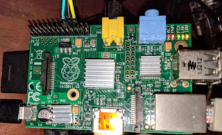 |
| RaspberryPi Connections |
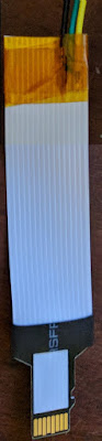 |
| Cable |
| You need to connect three pins. JTAG_TCK (SWCLK/TCK), JTAG_TMS (SWDIO/TMS) and a ground pin (VSS). The P1 header on the older model Pi is the same as the first 26 pins of the J8 header on the newer Pi2/3 (See here.)
I selected these pins:
- GPIO25 (Pin 22) for SWCLK/TCK (yellow wire)
- GPIO24 (Pin 18) for SWDIO/TMS (green wire)
- ground pin (Pin 20) between them (black wire)
I picked these mostly because that is the default config for OpenOCD on the RaspberryPi2/3. For the original RaspberryPi you have to copy the SWD pin definition from the RaspberryPi2 config file since they are not set up by default.
You will need a MicroSD cable that you can attach some wires to. I chose a cheap extension cable that I could cut up and solder to, but there are other debug breakout cables (like this one from sparkfun) if you want to pay a couple bucks more to have an easier time soldering. In the case of the extension cable I chose, every other wire in the ribbon is connected to ground. Yellow (SWCLK) is connected to pin 1, Green (SWDIO) is connected to pin 2 and ground is connected to the next ground wire since it was easy to get to.
|
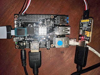 |
| ROCK64 connections |
On the ROCK64 board, click the cable into the MicroSD card slot. It is a spring loaded toggle connector so if you remove it you may have to push it in a second time to get into the "card inserted" position. I also have the serial adapter connected (the brown/white/red wires at the top) so I can monitor the boot process and break into u-boot.
Since the MicroSD slot is busy with JTAG, I am using the eMMC module to hold the linux image. I am currently using the
Ayufan xenial mate image. This uses the rock-chip binary blob boot loader, and u-boot/u-boot SPL to boot linux. This stock image does not force the JTAG pins to be enabled, and you will instead end up with MicroSD on these pins if you don't change it.
To start debugging with the JTAG adapter, break into u-boot and configure the JTAG force-enable by setting the GRF_GPIO1A_IOMUX to jtag_tms/jtag_tck and the GRF_SOC_CON4 grf_force_jtag bit (ROCK64 console):
U-Boot 2017.09-rc4-g22993de (Sep 14 2017 - 21:57:17 +0000), Build: jenkins-linux-build-rock-64-118
Model: Pine64 Rock64
DRAM:  4 GiB
MMC:   rksdmmc@ff500000: 1, rksdmmc@ff520000: 0
Card did not respond to voltage select!
mmc_init: -95, time 9
*** Warning - No block device, using default environment
In:    serial@ff130000
Out:   serial@ff130000
Err:   serial@ff130000
Model: Pine64 Rock64
normal boot
Net:   eth0: ethernet@ff540000
Hit any key to stop autoboot:  0
=> mw.l 0xff100010 0x00f000a0
=> mw.l 0xff100410 0x10001000
At this point you can run openocd and start debugging (though you will only get the single core that is currently running if you connect in u-boot.) If you instead wait until linux is booted (or re-run openocd) you will get all four cores attached (RaspberryPi console):
sudo openocd
Open On-Chip Debugger 0.10.0+dev-00226-g1c2e3d4 (2017-12-30-14:17)
Licensed under GNU GPL v2
For bug reports, read
 http://openocd.org/doc/doxygen/bugs.html
BCM2835 GPIO nums: swclk = 25, swdio = 24
adapter speed: 4000 kHz
Info : BCM2835 GPIO JTAG/SWD bitbang driver
Info : SWD only mode enabled (specify tck, tms, tdi and tdo gpios to add JTAG mode)
Info : clock speed 4061 kHz
Info : SWD DPIDR 0x2ba01477
Info : rk3328.cpu0: hardware has 6 breakpoints, 4 watchpoints
Error: target rk3328.cpu1: failed to set power state of the core.
At this point in time, OpenOCD supports debug of the AARCH64 cores, but does not include support for ETMv4. You can set breakpoints and read registers, but not currently configure tracing on this processor.
References
- ROCK64 Schematic
- RK3328 Technical Reference Manual


Hi, I'm trying these instructions but have run into a snag. OpenOCD is failing at target examination... it never sees a response to it's initial queries. I'm using a Raspberry Pi 3 B+, and I have a Firefly ROC-RK3328-CC board instead of the Rock64, but otherwise hardware is the same as your config.
ReplyDeleteOne potential difference is that recent versions of OpenOCD have a different config file syntax, so I rolled back to an earlier commit to use a version closer to what you were running. Do you know what commit you pulled from? Any advice on how to debug this? Thanks.
Thanks for your sharing, it helps me a lot and I think I'll watch your post more.
ReplyDeleteJTAG